Surface Treatment of Powder Metallurgy Parts: Finishes, Porosity and Common Problems
Updated 3 November 2026 · CSMFG technical guides
Surface treatment of powder metallurgy parts changes the surface to meet requirements for corrosion resistance, wear, cleanliness, appearance or lubrication. Options include mechanical finishing, steam treatment of suitable iron-based parts, conversion treatments, plating and compatible organic coatings. Select the treatment for the alloy, pore structure and service environment, then verify the finished component rather than judging protection by color alone.
Powder metallurgy makes the component from metal powder. Powder coating is a separate finishing process that applies and cures an organic powder on a substrate. The two terms describe different stages. This guide concentrates on pressed-and-sintered parts; MIM surfaces need their own alloy- and route-specific assessment. See powder metallurgy secondary operations for the complete post-sinter route.
Watch: PM Surface Treatment
Which surface treatment should you consider?
A PM surface treatment is a system selected for the substrate, pore function and service requirement. First identify whether the goal is edge preparation, lubrication, sealing, protection or appearance. Then define the important surfaces and the final inspection condition. CSMFG's SS304L Holder and 17-4PH H900 Cam Lever are specific substrate examples; the supplied part descriptions do not assign either one a coating.
| Documented route | Substrate / pore review | What the order must define |
|---|---|---|
| Blasting, polishing or grinding | Compatible alloy; protect fit surfaces. | Texture, edge condition and cleanliness. |
| Steam treatment / phosphating | Suitable ferrous PM; verify alloy suitability. | Complete system and post-treatment properties. |
| Oil impregnation | Preserve functional connected pores. | Lubricant and operating conditions. |
| Resin impregnation | Seal compatible connected paths. | Resin, cure and final leak requirement. |
| Copper, nickel, chromium or zinc plating | Clean and activate the substrate; review pore preparation. | Thickness locations, coverage, masking and final fit. |
| PVD or organic coating | Compatible preparation and thermal exposure. | Coverage, appearance, adhesion and service test. |
According to CSMFG's November 2026 confirmation, the documented routes are factory capabilities. Match the complete system to the drawing rather than selecting by color.

Why does porosity complicate surface treatment?
Open porosity is a connected pore network that can retain oil, cleaner or treatment liquid below the visible surface. Retained material can later bleed out or interfere with a finish, while local cavities can interrupt coverage. Closed pores and deliberately oil-retaining networks require different decisions, so bulk density alone cannot define the preparation route.
For example, the source Fe–Cu–C case identifies 100–150 µm cavities before any coating investigation. Those substrate features should be distinguished from a coating-generated pinhole. First inspect the uncoated part and identify whether pores must remain functional. Then select compatible cleaning, pore treatment, rinsing, drying and deposition steps. CSMFG's November 2026 confirmation includes documented impregnation and finishing capabilities; it does not prescribe one sequence for every stainless part. Henkel's vacuum-impregnation explanation provides external context on resin filling and curing. The complete route still needs the actual substrate, machining and service requirements.
What does steam treatment do to iron-based PM parts?
Steam treatment is a controlled oxidation process for suitable ferrous PM substrates. According to ASM International, a cited treatment range of 510–570°C forms iron oxide, commonly magnetite, at accessible surfaces and pores. The oxide can support surface hardness, wear resistance and sealing, but the same reference describes 10–20% reductions in tensile strength and ductility under the conditions discussed.
Those figures explain why steam treatment is a material-and-function decision rather than simply a black finish. First identify a compatible iron-based substrate and the properties required afterward. Then review dimensions, pore function and relevant service testing. CSMFG's source post-sinter note includes steam treatment among the documented capabilities confirmed in November 2026. The stainless SS304L Holder and 17-4PH H900 Cam Lever should not automatically receive that ferrous-PM route. The actual component needs an agreed treatment specification; the published temperature range is technical context, not a furnace recipe for every powder-metal alloy.
Can powder metal parts be nickel or zinc plated?
Yes, suitable sintered components can be plated using a qualified preparation and deposition route. The difficult question is how to achieve coverage and remove or control liquid retained in connected pores. Cleaning, pore-sealing decisions, activation, rinsing and drying need to be considered with the substrate and deposit. A bright top surface is insufficient evidence that the underlying part will resist corrosion in service.
Make the specification explicit: base alloy and condition, deposit system, thickness requirement, significant surfaces, masking, appearance and corrosion or adhesion acceptance criteria. Recesses and exposed edges may plate differently. Research on nickel plating and pore closure of iron PM parts treats substrate preparation and porosity as central variables; it does not establish a universal coating result for all PM parts.
Can powder metallurgy parts be powder coated?
They can be candidates for powder coating when the substrate and preparation are compatible with the coating system. The review should include oil and residue removal, accessible porosity, outgassing during heating, adhesion and whether the cure changes another part requirement. Discuss a qualified pretreatment and any required preconditioning with the finisher instead of prescribing one baking schedule for every alloy and pore network.
Powder coating also changes the effective dimensions and can cover contact surfaces, threads or locating bores. Define the masked areas and verify coating coverage at edges and recesses. A coating should not be used to conceal a crack or loose surface material. Qualify the system using parts that represent the actual powder, furnace, machining and cleaning route, including any impregnation or heat treatment.
Is a smooth finish the same as a sound surface?
No. Roughness, defects, cleanliness, coating adhesion and leakage are different characteristics. A roughness measurement describes texture over defined measurement conditions. It does not by itself prove the absence of isolated pinholes, a subsurface crack or a connected leakage path. Conversely, a deliberately porous filter or bearing can have a texture that would be unsuitable for a cosmetic component but necessary for its function.
For a sealing face, specify the required texture and the functional leakage criterion. For a visible bracket, define the significant surfaces and allowable marks. For a wear surface, consider the mating material and lubrication. Avoid transferring polished wrought-steel or additively manufactured test results to a pressed PM surface without checking that the material and process are comparable.
How do you investigate stains, pinholes, blisters or peeling?
| Symptom | Possible upstream contributors | Useful first check |
|---|---|---|
| Stain or later bleed-out | Retained oil, treatment liquid or pre-existing sintering deposits | Compare before- and after-finishing samples and cleaning records |
| Pinhole or local cavity | An existing substrate pore or particle-related cavity; coating-process effects are also possible | Inspect the uncoated surface and a cross section |
| Blister | Substrate damage, retained contaminants or gas, or a coating adhesion problem | Establish whether the feature existed before coating and identify the layer involved |
| Peeling or poor adhesion | Contamination, incompatible preparation or inadequate coating-process control | Compare preparation, adhesion and cure evidence on representative parts |
| Rust or corrosion at local areas | Incomplete coverage, damaged coating or retained residues | Examine edges, recesses and masked areas against the agreed test |
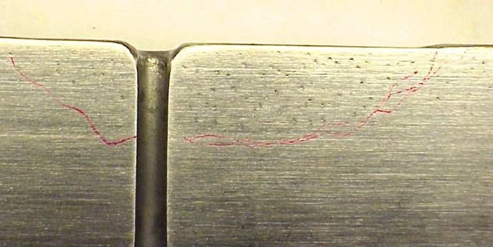
The illustrated sintered-part training cases include lubricant-related marks and cavities associated with coarse copper additions. Those are upstream substrate investigations, not proof of a defective plating bath. Identify the affected layer and manufacturing stage before selecting a correction. Use compositional analysis or metallography when the suspected mechanism requires evidence; a photograph alone cannot identify the chemistry of an inclusion.
How can coating thickness change a bore or outside diameter?
A deposited layer occupies space on every coated surface. In a simplified example, a uniform 5 micrometer deposit on each side of a 10.000 mm bore reduces the diameter by 0.010 mm, giving 9.990 mm. The same thickness on a 10.000 mm outside diameter increases it to 10.010 mm. These are geometric illustrations, not coating capabilities or CSMFG specifications.
Actual deposits can vary with geometry, process and position. A recess, edge or thread may not receive the nominal thickness uniformly, so a dimensional allowance based only on the average coating is incomplete. Agree the thickness acceptance range, measurement locations, masking boundaries and final fit with both the manufacturer and finisher. When a selected feature must be finished after coating, review whether the cut removes required protection or opens new paths through a sealed surface.
What should be checked before releasing a finished part?
A finish-release plan is the set of checks applied to the component after the operations that can change its accepted condition. Dimensions, coverage, adhesion, cleanliness and service performance answer different questions. A bright, uniform appearance alone does not establish that a bore fits, a coating adheres or a porous component is leak-tight.
For example, the CSMFG Cam Lever drawing identifies a 2.30 ±0.03 drilled feature, while the Holder is specified as SS304L, 6.6 g/cm³ and 45 HRB. First confirm the substrate and the surfaces that must remain functional. Second define coating thickness locations, masking boundaries and whether dimensions apply after the finish. Finally agree any adhesion, corrosion, wear or leakage test with its method, conditions and acceptance rule. CSMFG's November 2026 part data identifies the components but supplies no coating test result. Keep final inspection associated with the actual treatment system and material lot, especially when a preparation, sealant or cure changes.
Which factory treatment systems apply to which substrates?
CSMFG's documented finish capabilities include mechanical preparation, steam treatment for suitable ferrous PM, phosphating, oil or resin impregnation, metal plating and coating routes selected for the substrate. The post-sinter note names copper, nickel, chromium and zinc plating and describes pore preparation before plating. The MIM process document also identifies PVD as an appearance-finishing option. A system specification must connect the substrate, preparation and final deposit rather than merely naming a color.
The supplied SS304L Holder and 17-4PH H900 Cam Lever establish actual substrate/condition examples, but neither supplied part description names a coating. For example, steam treatment and phosphating for suitable iron-based PM should not be assigned to those stainless parts without a separate route review. The table below separates documented operations from the part-specific thickness, masking and performance criteria still needed in an order. Secondary-operation sequencing explains how machining and pore treatment affect the final finish.
How do the original stain cases guide surface preparation?
A surface stain can originate before any coating operation. The surface-problem PDF, pages 13–16, describes Metallub + MnS staining during dewaxing and a separate Fe–Cu–C / atomized iron + zinc stearate case. Local spectra in the second case show Mn/S-rich contamination. According to the source, correction proposals include greater dewax-zone gas flow, purer iron powder with lower manganese, and Amidwax instead of zinc stearate.
The source also lists RBO without defining the acronym, so no equipment or treatment is inferred from that label. First examine an uncoated substrate from the same route; then compare surface deposits with the powder, lubricant and furnace-removal conditions. A coating change cannot establish that the upstream contamination has been removed. The photographs below are labeled source cases, not coating pass/fail samples. No before/after inspected totals, salt-spray hours or adhesion result is supplied. See the sintering cases for blistering and Ni-rich flaking mechanisms.


Surface-treatment questions
Can a coating make a porous part leak-tight?
A coating is a surface layer, while pressure tightness is a functional requirement on the complete component. Coverage does not prove that every connected pore path has been sealed. A compatible impregnation process may address accessible paths, but the finished route must be evaluated under the relevant fluid, pressure and temperature conditions.
For example, CSMFG's SS304L Holder is specified at 6.6 g/cm³ and 45 HRB; those requirements do not define a leakage limit. The 17-4PH H900 Cam Lever is a different component and likewise has no supplied pressure-tightness requirement. First decide whether sealing is actually needed. Then identify final machining, any pore treatment, coating compatibility and the stage for the leak test. According to the factory information confirmed in November 2026, treatment choices are component-specific. A clear acceptance statement identifies the allowed leakage and test conditions instead of using the word “sealed” as a substitute for a measurable requirement.
Should dimensions be specified before or after coating?
A finished fit is a requirement on the component in the condition used for assembly. If a coating changes that fit, the drawing and inspection plan should identify the post-coating limit. Masking or selected finishing may instead preserve an uncoated functional surface. The manufacturer and finisher need the same datum and acceptance condition.
For example, a uniform 5 µm deposit on each bore wall reduces the bore diameter by 10 µm. An illustrative 10.000 mm bore would become 9.990 mm; an outside diameter changes in the opposite direction. Those numbers are geometry, not a CSMFG coating capability. First identify the relevant diameter, thread or contact face. Then allocate thickness, masking and any final machining. The Cam Lever detail's 2.30 ±0.03 drilled requirement must be assessed against its released units and final route. According to the November 2026 factory information, no finish was specified for the supplied Cam Lever or Holder examples.
Related reading: Powder metallurgy materials and porosity, sintering controls, and secondary-operation sequencing.
Discuss the alloy, environment and finished-part specification with CSMFG's powder metallurgy and MIM team.