Powder Metallurgy Materials: How to Choose Metal Powders for a Part
Updated 3 November 2026 · CSMFG technical guides
Powder metallurgy materials range from iron and low-alloy steels to stainless steels, copper-based alloys and specialized hard or magnetic materials. Selection starts with what the part must do: carry load, resist wear or corrosion, conduct electricity, retain lubricant or control magnetic behavior.
The material is not just a powder grade. The manufacturing route, additives, compacted density, sintering cycle and secondary processing all affect the final part. A material qualified for one powder metallurgy route cannot automatically be substituted into another.
Watch: Powder Metallurgy Materials
What material families are used in powder metallurgy?
A powder-metallurgy material family is a starting group defined by composition and intended function; the production route and final condition narrow the actual choice. CSMFG's frequently supplied grades include 304, 316, 17-4PH, SKD11 and Fe2Ni, according to the November 2026 factory confirmation. The SS304L Holder and 17-4PH H900 Cam Lever are separate examples of how a grade becomes a component specification.
| Family | Function to investigate | Selection check |
|---|---|---|
| Iron / low-alloy steel | Structural load, gears or cams. | Density, final condition and protection. |
| Stainless steel | Corrosion exposure and structural function. | Exact grade, environment and final surface. |
| Copper / bronze | Lubricant storage or conduction. | Pore function and the required property. |
| Tool / hard materials | Wear contacts or tooling features. | Hardness, toughness and mating conditions. |
| Magnetic / specialty alloys | A defined functional response. | Appropriate final-part test and processing. |
First define the component's function. Then compare the available material and processing route against that requirement.
How do powder characteristics affect manufacturing?
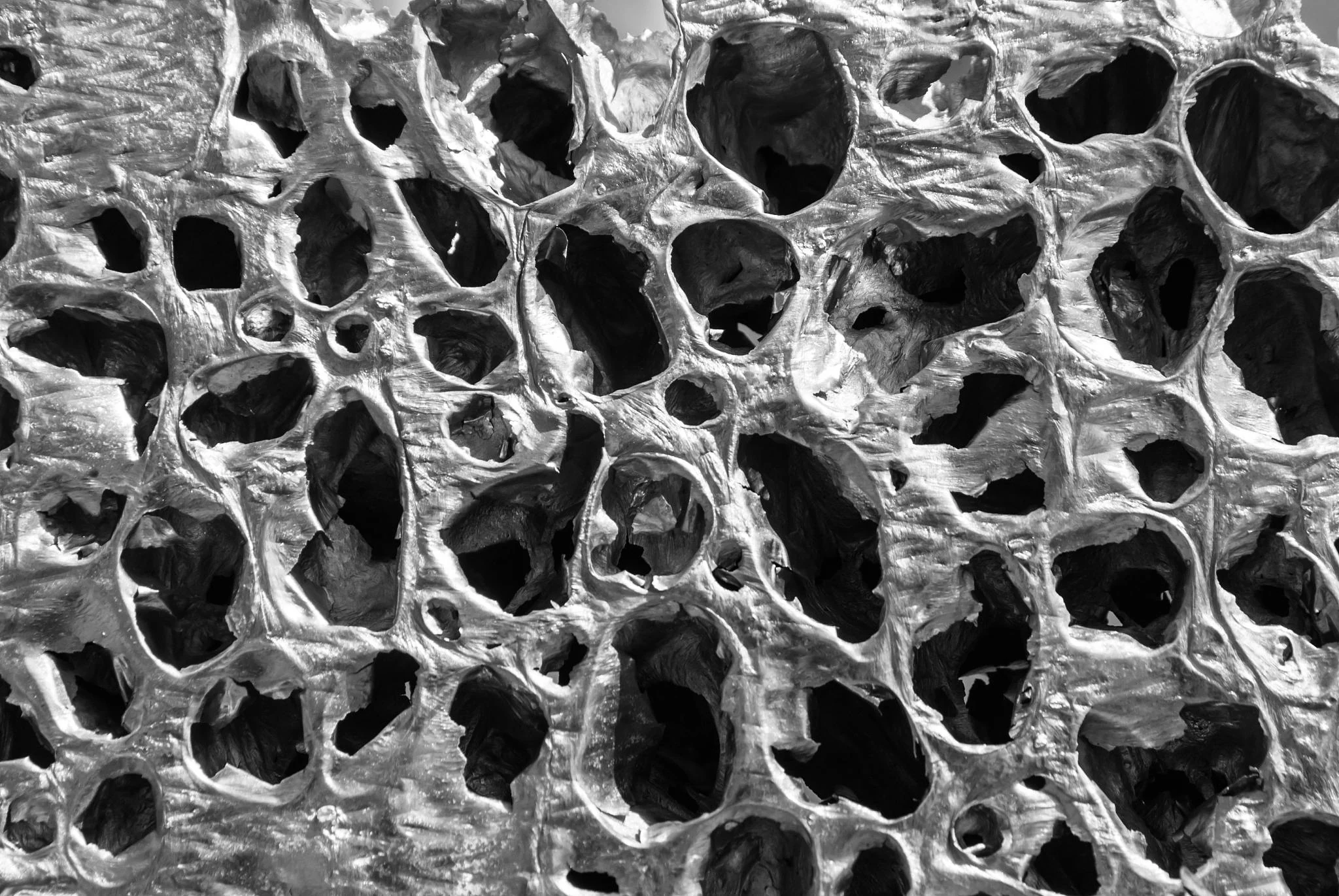
Particle size distribution, shape, chemistry and surface condition affect powder flow, die filling, compaction and sintering. Fine powder has more surface area and can sinter readily, but it can also be harder to handle and more sensitive to oxidation. Conventional press-and-sinter and MIM typically use different powder and feedstock systems, so compare a qualified recipe rather than only the alloy name.
Powder selection involves an important trade-off: powder that is easy to sinter is not necessarily the easiest to mix, mold or debind. The producer must optimize the complete route. That is a reason to ask for material traceability and control of the entire process, not just an incoming certificate.
How do you specify a powder metal material?
A powder-metal material specification should connect the alloy and final processing condition to the part's function. State the required chemistry or recognized material designation, heat treatment, critical properties and test method. For example, an oil-retaining bronze bearing needs an agreed porosity and lubricant requirement, while a loaded steel gear may need a defined density and fatigue qualification.
Indicate whether results apply before or after impregnation, coating or machining. Ask the manufacturer to identify the qualified powder mix, process route and acceptance plan rather than substituting a wrought-material datasheet.
- Describe loading: static, impact, wear and fatigue where relevant.
- Define operating environment, temperature and corrosion or lubrication needs.
- Name the required alloy or applicable material standard and final condition.
- Specify functional properties, test method and sample location or coupon requirements.
- Agree on density, hardness, porosity or leak testing only where related to function.
- Validate any heat treatment, impregnation, plating or machining in the production route.
For properties and process explanations, see MPIF’s introduction to powder metallurgy. The drawing and agreed acceptance plan remain the governing requirements for your part.
What is the difference between open and closed porosity?

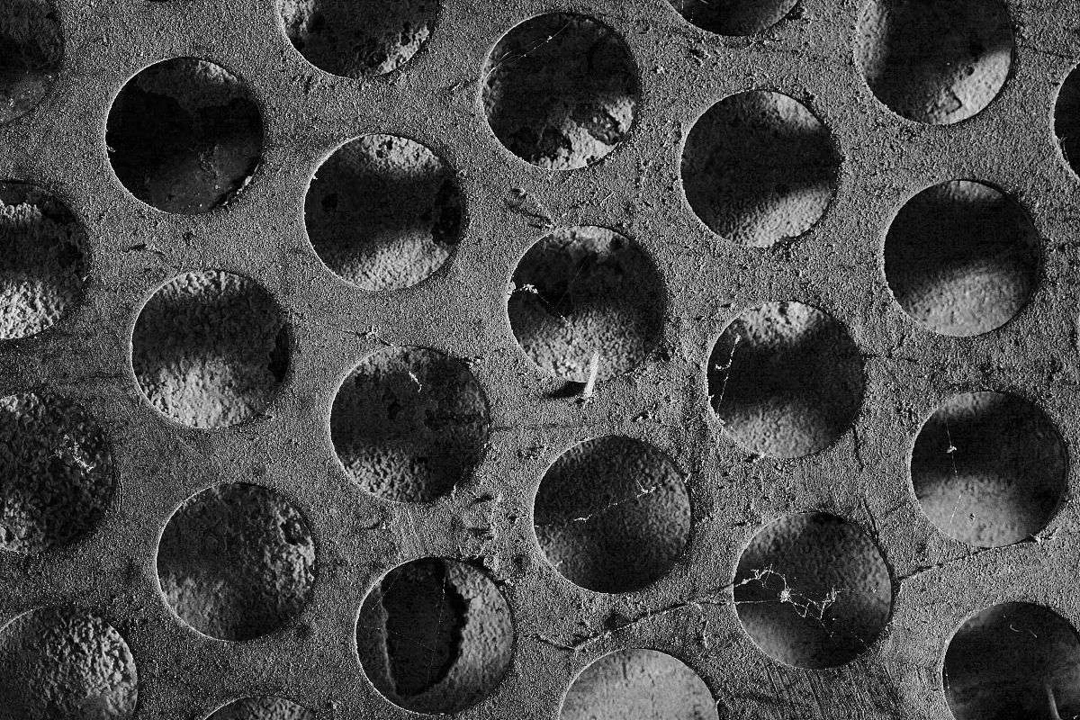
Open porosity is pore space connected to the surface; closed porosity is isolated within the material. The distinction matters because connected pores can retain lubricant, permit fluid flow or trap cleaning and plating solutions. For example, a self-lubricating bearing relies on an accessible pore network, while a pressure housing may require sealing and a leak test.
Average density alone does not show whether a connected leakage path exists. Specify the intended function and test the finished part after impregnation, machining or coating. See surface treatment for preparation and retained-fluid checks.
Can additive particle size leave a surface cavity?
Yes. The Fe–Cu–C case in the surface-problem PDF, pages 17–18, identifies 100–150 µm cavities near copper-rich regions. The input copper powder is described as 100 mesh, and the proposed correction changes it to 200 mesh. The source's micrographs retain a 100 µm scale bar and identify nearby fine pearlite plus martensite. According to the case description, additive distribution and local composition belong in the investigation, not just the average base-powder size.
The document does not name a mesh standard or report before/after defect counts and inspected totals. Preserve the source notation instead of converting mesh to a universal particle diameter. For example, inspect a similar cavity against the actual copper grade, lot, mixing route and local microstructure before changing the blend. The corrective proposal is specific to the observed morphology; it does not establish that all finer powders improve every PM part. See surface treatment for the consequences of pinholes already present in the substrate.


How should material options be compared?
A material comparison is a review of complete finished-part options under the same service requirement. Match the drawing, quantity, final condition and inspection basis before comparing unit price. A wear contact, porous bearing and corrosion-exposed bracket need different acceptance questions even when all are made from metal powders.
For example, CSMFG's SS304L Holder is specified at 6.6 g/cm³ and 45 HRB, while the 17-4PH H900 Cam Lever has a different grade and condition. The November 2026 price examples also use different order thresholds. First identify the failure mode, environment and assembly requirements. Then compare the proposed alloy, density or pore function, thermal route and surface treatment. Include relevant testing and downstream processing in the accepted-part cost. The MIM material guide addresses stainless and tool-steel choices; the published MIM property reference supplies clearly attributed industry values rather than relabeling external data as CSMFG measurements.
What does the SS304L Holder specification establish?
The CSMFG Holder / Halter is a conventional-PM stainless example specified as SS304L, MPIF Std. 35, 6.6 g/cm³ and 45 HRB. According to CSMFG's November 2026 part information, the reported price is RMB 4.40 per piece above 10,000 pieces. The production photo and drawing identify the associated geometry, including two M6 thread callouts. The density and hardness are supplied requirements for this component, rather than universal values for stainless powder metallurgy.
The example shows how an actionable material description connects alloy, a material-standard reference and two property requirements. A complete purchase specification should also identify the relevant standard edition, final processing condition and inspection basis. The supplied example does not include a laboratory report or final coating specification. First keep the stated grade distinct from 304 or 316; then review the secondary operations and finish with the drawing. The full cost case provides the original part images and commercial scope.

Which incoming checks help control the powder blend?
An incoming powder check is a verification of the material variables that can affect filling, compaction and sintering. CSMFG's documented checks include composition, particle-size distribution, apparent density and flowability. Supplier review, dry storage, FIFO and recorded nonconforming-material disposition help preserve that identity until the powder reaches production.
The source Fe–Cu–C case illustrates why an additive needs its own review. Microscopy identifies 100–150 µm cavities near copper-rich regions, and the proposed correction changes copper powder from 100 to 200 mesh. Another source case links contamination at a core rod to a local crack. First retain the base-powder, additive and lubricant identity with the lot. Then compare normal and defective locations before changing pressure or furnace conditions. According to the factory information reviewed in November 2026, incoming and process controls work together; a satisfactory chemistry result does not establish the flow or cleanliness of the entire blend. The sintering guide follows those inputs downstream.
Powder metallurgy material questions
Which metals can be made into powder metallurgy parts?
Powder metallurgy materials include iron and low-alloy steels, stainless steels, copper-based materials and specialty systems. Selection starts with the function: a loaded gear, a corrosion-resistant component and an oil-retaining bronze bearing do not require the same pore structure or final condition. Powder chemistry, particle distribution, compaction and sintering all influence the finished result.
For example, the illustrated iron-copper-carbon training case connects coarse copper additions with local pinholes; the finding is a reason to investigate a similar morphology, not a universal particle-size rule. Confirm the available grade and qualified properties with the supplier.
Why use bronze powder for a bearing?
A suitably designed porous bronze part can be impregnated with lubricant. Its connected pore structure and the chosen oil are functional requirements, so the buyer should specify the bearing application and acceptance tests rather than requesting maximum density by default.
Related reading: Explore the MIM material guide, the press-and-sinter process, and sintering and porosity.
Discuss your part and material requirements with CSMFG’s powder metallurgy team.
Match the pore structure to secondary-operation requirements and surface protection.