MIM Debinding and Sintering: Why Binder Removal and Furnace Control Matter
Updated 3 November 2026 · CSMFG technical guides
Debinding is the controlled removal of the temporary binder from a molded powder-metal component; sintering then develops particle bonds and changes density and dimensions. The two stages have different purposes. A green part needs enough binder to flow into the mold and survive ejection, while a brown part needs open removal paths and sufficient support for the remaining thermal cycle.
CSMFG's documents describe solvent, thermal and catalytic routes for compatible feedstocks. According to MIMA's process overview, primary removal leaves a binder backbone, with the remaining binder removed during the early furnace cycle. For example, the 17-4PH H900 Cam Lever must be assessed through its lever profile and pivot region, rather than assigned a cycle solely from its alloy name. First match the feedstock to the removal route; then review the thickest section, fragile projections, loading and final condition. The sections below explain the controls and distinguish MIM binder removal from conventional-PM lubricant cases.
Watch: MIM Debinding and Sintering
What debinding methods are used?

- Solvent or water extraction: A compatible liquid removes a soluble portion of the binder. The selected fluid, time and temperature depend on the binder system.
- Catalytic debinding: A suitable binder component is chemically broken down under controlled conditions. This is specific to compatible feedstocks and equipment.
- Thermal debinding: Heat decomposes and removes binder components. A controlled schedule limits pressure buildup and damage.
Methods can be combined; one label does not describe every step of a particular feedstock. The aim is to create pathways for binder removal while maintaining enough shape and strength for handling and sintering.
Why do thick sections create risk?
Binder must leave the interior of the part. As section thickness and escape distance increase, the cycle may need more time or a different design. Rapid removal can contribute to blistering, cracks or distortion. Coring a thick boss can reduce material and escape distance, provided the remaining section still meets strength and tooling requirements.
Avoid changing a debinding schedule simply to shorten production time. Validate the change using representative cross-sections and the thickest features, and check downstream properties and defect rates. The appropriate schedule is a supplier-controlled process parameter, not a universal number.
What happens during sintering?
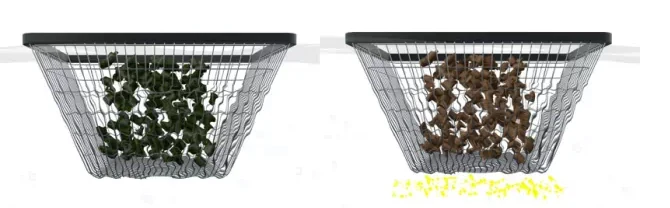
Sintering is a controlled thermal treatment that bonds the metal-powder skeleton after primary debinding. The early furnace stages remove residual binder; the later exposure develops the required microstructure, density and dimensional change. Furnace atmosphere, temperature, time and cooling must suit the alloy and the intended final condition.
For example, CSMFG's 17-4PH H900 Cam Lever has a shaped arm and a pivot feature, so both support and subsequent operations belong in the thermal-route review. A satisfactory outside dimension does not establish the required condition at the pivot. First check that binder-removal products can escape without damaging the skeleton. Then control furnace loading and support so the component can shrink without unacceptable sag or contact marks. The MIMA process explanation describes batch and continuous furnace routes. Neither route supplies a universal temperature or residence time for every stainless component; the released material and part requirements determine the production cycle.
What should a buyer verify?
A debinding-and-sintering review is a check of the feedstock, removal route, furnace load and finished-part requirements as one connected process. First identify which binder family and primary-removal method are used. Second establish how green and brown components are supported, released and traced into the thermal batch. Finally agree the dimensions and material characteristics that are checked after the complete route.
For example, the CSMFG Cam Lever is specified in 17-4PH H900 and has a drilled pivot callout. The review should distinguish the sintered shape from the later drilled and heat-treated condition. CSMFG's November 2026 source information identifies vacuum or protective-atmosphere sintering options and emphasizes feedstock uniformity, carbon control and loading. Ask for the controls relevant to the actual grade and component rather than a confidential recipe. Use the process-control overview and secondary-operation guide to identify where acceptance could change between stages.
What do setters and part spacing do?
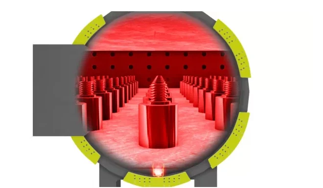
A MIM sintering setter is a support that holds the component as the part softens and shrinks in the furnace. The support must balance shape control with movement: friction or uneven contact can leave marks or contribute to distortion. For example, a long projection may need a shaped support, while its critical face must remain free of unacceptable contact marks.
Part spacing and loading must also suit the qualified furnace and binder-removal route. Compare dimensions and visible marks by position in a representative load before releasing the support design; one favorable sample does not establish repeatability.
What can go wrong between stages?
MIM defects can originate in one stage and become visible in another. Ejection can damage a green part; rapid or uneven binder removal can cause cracks or blisters; poor furnace support can distort a fragile shape. Inspect representative samples after molding, primary debinding and sintering to identify when the defect first appears.
For example, if a crack is already present in the green part, changing only the sintering temperature may not solve the cause. Link the inspection result to feedstock lot, cavity, handling and thermal batch. Confirm the corrective change with representative production conditions.
For new products, validate the thickest section, longest projection and most critical datum relationship. If a change to the feedstock or furnace loading is proposed later, agree on the checks needed before releasing the revised process.
Which binder-removal controls are described by the factory?
CSMFG's documented debinding routes include solvent extraction, thermal removal and catalytic removal for compatible feedstocks. The process description names the Catamold catalytic system and a dedicated catalytic furnace. The special-process document explains that binder must escape progressively through interparticle channels while the compact retains its shape; an excessive removal rate can produce blisters or cracks.
First identify the binder family and the component's thickest escape path. Then distinguish primary removal from the thermal removal of the residual backbone. The factory references list wax/oil/polymer thermoplastics, gel, thermoset and water-soluble systems, but they do not prescribe one cycle for every alloy and section thickness. According to CSMFG's November 2026 material confirmation, stainless grades including 304, 316 and 17-4PH are frequent production choices. A change in compatible feedstock or geometry still calls for review of the removal route. The Cam Lever case supplies an actual 17-4PH H900 component context.
What can a PM dewaxing case teach about loading?
A furnace-position pattern is evidence worth recording before changing a binder-removal cycle. In the pressed-PM Fe–P–C reference case, Fe3P at 1120°C for 30 minutes is associated with blistering on the first component in each sintering boat. According to the surface-problem PDF, pages 6–7, the proposed correction is greater dewax-zone gas flow to limit lubricant deposition; a sacrificial leading component is also described.
The example is conventional PM, where lubricant removal differs from MIM feedstock debinding. Its transferable lesson is the investigation method: map affected positions, inspect the entry region and compare deposits with unaffected parts. A separate Ni-containing PM case links incomplete dewaxing and premature entry into the hot zone with flaking. The source proposes longer dewaxing residence and flow adjustments, but supplies no universal gas setting or validated MIM recipe. Follow the sintering case analysis for the formulation-specific evidence.

Debinding and sintering questions
Why is binder removed before sintering?
MIM binder is removed so the powder skeleton can be consolidated into a metal component during the qualified furnace cycle. Primary debinding removes a portion of the binder while the remaining structure holds the shape; residual binder is often removed thermally before or during early sintering. The method must match the feedstock.
Thick sections create longer escape paths and can be sensitive to overly rapid removal. For example, compare the center and surface of a thick boss if cracking starts during debinding. The MIMA process overview describes the feedstock-dependent sequence.
Can debinding and sintering occur in the same furnace?
Some equipment and feedstock systems combine thermal debinding and sintering in one controlled furnace cycle. Others require a separate primary solvent, water or catalytic step. The correct sequence is specific to the qualified binder system and equipment.
Related reading: Understand MIM shrinkage and tolerances, troubleshoot MIM defects, or compare powder metallurgy sintering routes.
For help assessing a part, see CSMFG’s powder metallurgy and MIM services.
Review the planned secondary operations after sintering before approving the final inspection condition.