What Is Metal Injection Molding? Process, Applications and Design Trade-Offs
Updated 3 November 2026 · CSMFG technical guides
Metal injection molding is a powder-metallurgy route that forms metal powder and a temporary binder in an injection mold, removes binder and sinters the resulting shape. The metal is not injected as a fully molten casting alloy. The route combines mold-defined detail with a later thermal process that develops the finished metal body.
For example, CSMFG's Cam Lever is a MIM component specified in 17-4PH H900. Its supplied drawing includes a drilled pivot feature, showing why the manufacturing route includes both shaped geometry and selected secondary operations. According to the factory information confirmed in November 2026, frequently supplied materials include 304, 316, 17-4PH, SKD11 and Fe2Ni. First review the component's function, geometry and quantity; then plan molding, debinding, sintering and final inspection together. The MIMA process overview provides the industry stage sequence. The CSMFG examples below connect that sequence to actual part drawings and commercial requirements.
Watch: Metal Injection Molding Process
How does the MIM process work?

- Prepare the feedstock. Fine metal powder is mixed with a binder system and usually supplied as pellets. The binder gives the powder mixture the flow and temporary strength needed for molding.
- Injection mold the green part. Heated feedstock fills the cavity and cools. The ejected part is larger than the intended finished component because shrinkage must be allowed for.
- Remove binder. Depending on the feedstock, primary debinding may use solvent, water, a catalytic process or heat. The fragile part must retain enough shape for handling.
- Sinter the part. A controlled thermal cycle removes remaining binder and bonds metal particles. The part densifies and shrinks as it is heated.
- Finish and inspect. Features may be machined, heat treated, passivated or coated where required; inspection verifies agreed dimensions and properties.
The Metal Injection Molding Association’s process overview explains these stages and the role of the binder. A critical distinction is that the metal powder is not injection molded as fully molten metal; it is carried into the mold by the binder and consolidated later.
What parts are good candidates for MIM?
A good MIM candidate is a small metal part whose three-dimensional features justify dedicated tooling at the expected production volume. A latch with a contoured arm, bore and side feature may benefit when a mold forms most of the geometry; a simple turned pin may not. Examine the alloy, dimensional requirements and post-sinter operations alongside shape.
For example, a thick boss can slow binder removal and an unsupported projection may need a sintering setter. Mark load-bearing and cosmetic surfaces on the drawing before requesting a manufacturing review.
MIM is often considered for locking parts, small gears, connector hardware, instrument components and appliance mechanisms. A safety-critical or medical use requires application-specific material qualification and validation; the process name alone is not evidence of suitability.
What are the limitations?
MIM is not unlimited in shape or size. Mold opening, core removal, powder flow, binder removal and furnace support constrain geometry. Thick sections can extend debinding time, while unsupported projections can distort during sintering. Tight tolerances, threads and critical surfaces may need secondary operations.
The material designation also needs context. A sintered MIM alloy can differ from wrought material of the same nominal grade because processing, residual porosity and heat treatment differ. Agree on test methods and acceptance criteria for the actual production route.
How should a buyer start?
A MIM feasibility review is a joint check of geometry, material, quantity and final acceptance requirements. A 3D model alone does not identify which surface locates the assembly or which feature needs machining. For example, the CSMFG Cam Lever drawing calls for a drilled diameter of 2.30 ±0.03 and a countersink; the component is specified in 17-4PH H900. Those details matter to tooling and finishing decisions as much as the outside profile.
First mark the assembly datums, loaded sections, fit dimensions and appearance surfaces. Then provide order quantities and identify any corrosion, wear or proof-load requirement. Ask CSMFG to distinguish molded features from drilled, tapped, sized or otherwise finished features. The November 2026 reference price above 2,000 Cam Lever pieces applies to its own component scope. A new design needs a route and price review using the complete drawing. See MIM cost planning for the commercial information to request.
What does the part look like at each stage?
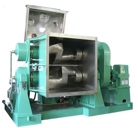
A green component looks like the final design but contains binder and is intentionally oversize. A brown component has had much of that binder removed, so it can be porous and delicate. After sintering, the part has shrunk and developed metal-to-metal bonds; it may still need finishing and inspection. Handling practices appropriate to a finished component can damage earlier-stage parts.
This sequence also explains why an injection-molded plastic prototype is useful for checking general geometry but cannot establish final MIM dimensions or strength. A first-off production trial needs the actual feedstock, mold, debinding and sintering route. Check features across the chosen inspection datums after all planned secondary work.
Is MIM the same as die casting?
No. Die casting fills a mold with molten metal, whereas MIM molds powder mixed with a binder and then sinters it. Die casting is widely used for appropriate aluminum and zinc alloys; MIM is often assessed for small complex parts in steels and other powder-processable materials. Each route has its own geometry, tooling and material constraints.
What does a CSMFG production example add to the process explanation?
The CSMFG Cam Lever is a practical MIM example specified in 17-4PH H900. The lever profile, pivot region and drilled-hole callout connect the general process stages to an actual part: molding creates the powder-and-binder shape, debinding removes the temporary binder, sintering develops the metal body, and secondary processing brings selected features to the drawing requirements. The exact operation sequence belongs in the approved route.
According to CSMFG's November 2026 factory information, commonly supplied grades include 304, 316, 17-4PH, SKD11 and Fe2Ni. Material selection therefore starts with available production experience, then narrows to the component's final condition and service requirement. The Cam Lever example is priced at RMB 2.40 per piece above 2,000 pieces; that reference is specific to the illustrated part. See the complete cost example for the supplied drawing, photos and quotation boundaries.

Which factory controls connect powder selection to final inspection?
CSMFG's documented process controls cover raw-material composition, particle-size distribution, apparent density and flowability, followed by feedstock uniformity, molding conditions and controlled binder removal. The factory's special-process document identifies mixing temperature and shear as important because excessive temperature can degrade binder or separate powder from binder. A uniform-looking molded surface alone does not establish uniform internal material.
First, incoming material is checked and stored to prevent moisture, contamination and mix-ups. Second, the binder family is matched to solvent, thermal or catalytic removal as applicable. Furnace temperature, time, atmosphere and loading are then controlled for the selected alloy. The factory's process presentation also specifies FIFO inventory traceability and recorded disposition of nonconforming powder. These controls explain why changing powder, binder or a thermal route needs a manufacturing review even when the drawing is unchanged. For defect-specific evidence, follow the troubleshooting guide.
Metal injection molding questions
Is metal injection molding the same as plastic injection molding?
The molding equipment and tooling principles are similar, but MIM feedstock contains metal powder and a temporary binder. A MIM part must then be debound and sintered; a conventional thermoplastic part normally reaches its molded state by cooling. The extra thermal stages affect dimensional planning and cost.
What is the difference between a green and a brown MIM part?
A green MIM part is the molded powder-and-binder shape before primary debinding. A brown MIM part is the fragile shape after much of the binder has been removed; residual binder and porosity depend on the qualified feedstock and method. The distinction matters when investigating damage: compare a sample immediately after molding with another after debinding.
A crack appearing between those stages calls for checks on handling, section thickness and binder removal. Sintering then bonds the metal particles and changes dimensions. The Metal Injection Molding Association describes the stages and the link between binder and debinding method.
Related reading: Compare MIM with conventional press-and-sinter, review MIM design guidelines, or explore MIM materials.
For a part-specific manufacturing review, see CSMFG’s powder metallurgy and MIM services.
Plan the final machining, heat treatment and finishing with the secondary-operations guide.