Common Metal Injection Molding Defects: Causes, Checks and Corrective Actions
Updated 3 November 2026 · CSMFG technical guides
A MIM defect is a departure from the required shape, internal integrity, material condition or surface quality of an injection-molded metal component. Common symptoms include incomplete filling, cracks, blisters, voids, distortion and dimensional drift. The stage where a defect becomes visible is not necessarily the stage where the damage began.
First compare green, debound and sintered samples from the same feedstock and tooling route. Then connect the defect location to gates, cores, ejection, handling and furnace support. For example, the CSMFG Cam Lever combines a shaped arm with a pivot feature in 17-4PH H900; damage at the pivot deserves a different functional assessment from a cosmetic mark on a clearance face. The factory's November 2026 source set also contains conventional-PM microscopy cases. Those cases provide evidence-led investigation examples while retaining their actual process labels. The PIM International defect review explains why defects can cross stage boundaries.
Watch: MIM Defect Investigation
What causes common MIM defects?
A defect map is a comparison between the observed symptom and the manufacturing stage capable of producing it. Short shots point first toward filling; a crack near a core calls for flow-front, ejection and handling checks; distortion calls for a geometry and support review. The same visual symptom can still have more than one cause.
For example, the pressed-PM source case identifies 100–150 µm cavities near copper-rich regions, while a separate case identifies a contaminated crack region at a tool location. Those observations justify different correction paths. First establish the stage and location, then compare material, tooling and thermal records. In a MIM Cam Lever, use the actual 17-4PH H900 route and pivot geometry for the investigation. The table below gives starting checks, rather than a predetermined furnace adjustment for every defect.
| Symptom | Stage / variable to check | Evidence |
|---|---|---|
| Missing detail | Filling, gate and vents. | Fill pattern and shot consistency. |
| Crack | Weld line, ejection or handling. | Stage samples and a local section. |
| Blister / void | Segregation or binder removal. | Feedstock and thermal records. |
| Warp / drift | Support, shrinkage or measurement. | Datums, cavity and load position. |
Why can a crack appear only after sintering?

An injection-molded green part can contain a weak weld line or a small ejection crack that is difficult to see. Binder removal and sintering may open the defect or make it more visible. Map its location against gates, cores and ejector pins, then compare green, debound and sintered parts before changing the furnace recipe.
A crack that always starts at the same side of a cross-hole suggests a different investigation from random cracks across all cavities. Sectioning, magnification and, where justified, nondestructive inspection can distinguish a surface mark from an internal discontinuity. Choose the method according to the failure risk.
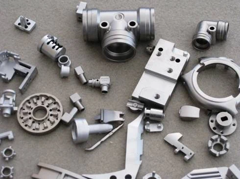
How do you investigate blistering and warpage?
A MIM blister and a warped part can have different causes and should be investigated separately. A blister may involve trapped material or binder removal; warpage can reflect unequal shrinkage, geometry, support or furnace loading. First establish when the symptom appears by comparing molded, debound and sintered samples.
For example, a blister visible before sintering points the team toward earlier handling and debinding evidence; distortion concentrated at one furnace position calls for a support and loading review. Record feedstock lot, cavity and thermal batch, then validate one corrective change under representative conditions.
For warpage, compare the direction of distortion with wall thickness, gate location and the way the part rests on its sintering setter. A geometrical change, revised support or controlled loading may help. Record each trial separately and measure a representative sample across cavities and furnace positions.
What records help prevent recurrence?
A recurrence-control record is the connection between an approved correction and the material, tool, thermal route and inspection used afterward. Keep the part revision, feedstock lot, cavity, machine, debinding batch, furnace load and final inspection together. A later supplier or process change should be reviewed against the characteristics that justified the original release.
For example, the source graphite-agglomeration case uses Distaloy AE+0.7C at 1250°C for 20 minutes and proposes a mixing-system change. A separate Ni-rich flaking case changes dewaxing and agglomeration controls. The records must identify which mechanism and which change belong to each component. First retain the defect photographs and normal comparison. Then record the actual correction, inspected totals, defect counts and confirmation period where those results exist. CSMFG's documented FIFO and raw-material traceability support that chain. The powder-material guide connects incoming checks with the downstream observations.
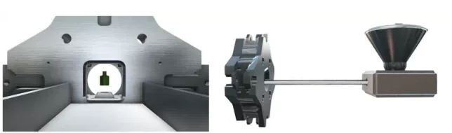
A practical sequence for a defect investigation
A controlled defect investigation is a sequence that separates containment, diagnosis, correction and confirmation. First identify affected parts, feedstock lots, cavities and furnace loads. Photograph the symptom with its location and scale, then compare the earliest available stage samples before changing process settings. The aim is to locate the origin rather than make the final symptom less visible.
For example, the source Fe–P–C case places blistering on the first component in each sintering boat at 1120°C for 30 minutes. The repeated position provides evidence for a loading and dewaxing review. A CSMFG MIM component instead needs the compatible binder-removal and tooling checks for its own route. Record each proposed correction, the variables held constant and the relevant dimensions or functional tests. Confirmation should report defect counts together with inspected totals and later-lot observations. The source teaching cases do not provide those outcome counts, so their correction proposals remain distinct from quantified improvement results.
When is a cosmetic mark also a functional problem?
A functional surface defect is a mark or discontinuity that can affect the specified fit, seal, sliding contact or load path. Location matters: a gate vestige on a clearance face and a crack at a loaded pivot are different acceptance questions. A visually small feature can therefore require more attention than a larger mark on an unloaded surface.
For example, CSMFG's 17-4PH H900 Cam Lever drawing identifies a drilled pivot diameter of 2.30 ±0.03. A line near that feature should be compared with the tool layout, drilling and handling stages, then examined by a method suited to the failure risk. First distinguish a parting line or machining witness from a real discontinuity. Next evaluate the relevant dimensional or functional requirement in the final condition. The factory examples confirmed in November 2026 establish the component context, not a universal cosmetic tolerance. The surface-treatment guide explains why polishing or coating is not evidence that an underlying crack has been removed.
What can pressed-powder examples contribute to a MIM investigation?
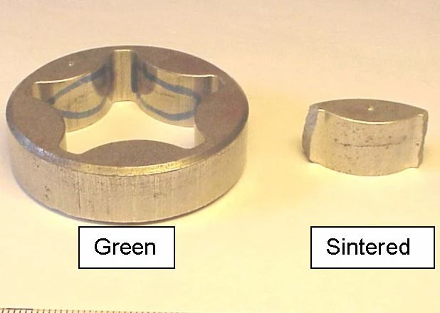
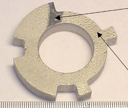
Pressed-and-sintered PM examples can illustrate how to organize an investigation, but their material chemistry and forming mechanisms must not be labeled as MIM results. The crack and blister training cases shown below demonstrate two useful questions: does the defect follow a tool location, and does it follow a furnace-loading position? Compare samples before and after each stage to find where the damage first appears.
A MIM review should then test causes appropriate to its own feedstock, molding, debinding and sintering route. For example, a tool-associated crack may require checking filling, weld lines and ejection, while thermal damage may require examining binder removal and support. The pressed-PM images below are training comparisons; they do not establish the cause of a defect in a MIM component.
What evidence linked the pressed-PM crack to tooling?
The pressed-PM crack case is a tool-location investigation supported by stage photographs, a local section and EDS comparisons. According to the surface-problem PDF, pages 8–11, the crack region has lower local density and more contamination than the normal region. The source identifies insufficient demagnetization at part of a core rod, where retained iron powder contaminated the compact. Effective demagnetization of the die and punches is the correction described.
The green-versus-sintered photographs help locate the process stage; they are not a before/after improvement trial. No defect count, inspected total, subsequent-lot result or quantified residual-field limit is supplied. For example, the case supports checking a repeatable tool-associated crack against powder retention and the local section before changing a furnace cycle. A MIM investigation must also check its own filling, weld lines and ejection mechanisms. Keep the pressed-PM evidence labeled by its actual forming route.

How were graphite and foreign inclusions distinguished?
The surface-problem PDF separates two superficially similar PM defects using local material evidence. In the Distaloy AE+0.7C case at 1250°C for 20 minutes, the defect region is described as carbon rich relative to the normal region. The proposed mixing change is Starmix. In the Fe–Cu–C / Distaloy ACu case, microscopy instead shows no nearby agglomeration evidence, while large foreign particles are found in the powder feed shoe.
According to pages 12 and 19–21, the two observations lead to different correction paths: improve control of graphite distribution in the first case and investigate introduced contamination in the second. A dark cavity alone does not identify either cause. Retain the defect location, normal comparison, blend identity and feed-system evidence together. The source supplies photographs and corrective reasoning, but no before/after inspection denominators or later-lot confirmation. See the powder-material controls for incoming checks and additive-distribution considerations.


MIM defect questions
What causes a weld line in a MIM part?
A MIM weld line, also called a knit line, forms where separate streams of powder-binder feedstock meet in the mold. Flow path, gate location, venting, temperature and feedstock behavior can affect how the streams join. A visible line is not automatically a structural failure, but a line crossing a highly stressed root warrants a specific inspection or functional test.
For example, compare the line position with the mold layout and examine green, debound and sintered samples. Change one justified variable at a time and verify both appearance and the part's required performance.
Is every visible line on a MIM part a crack?
No. A parting line, flow mark or gate vestige can be visible without being a crack, but appearance alone is not always conclusive. Compare the location with the tool layout and use an agreed inspection method when integrity is in question.
Related reading: See MIM design guidelines, understand debinding and sintering, and review shrinkage and tolerances.
Discuss recurring part defects or a new drawing with CSMFG’s powder metallurgy and MIM team.
If a mark appears after finishing, compare substrate and coating stages using the surface-treatment troubleshooting table.