Powder Metallurgy Process: How Press-and-Sinter Parts Are Made
Updated 3 November 2026 · CSMFG technical guides
Conventional powder metallurgy makes a component by blending metal powders, compacting the blend in a die and sintering the compact in a controlled furnace. The process is commonly called press-and-sinter. It can make repeatable shapes close to their final dimensions, often with less cutting than machining a part from solid stock.
Powder metallurgy is a family of processes. Metal injection molding, isostatic pressing and some additive manufacturing routes also use powders, but their forming steps differ. The Metal Powder Industries Federation describes press-and-sinter as the basic conventional route.
Watch: Press-and-Sinter Process
What are the steps in press-and-sinter?
1. Select and blend the powder
A powder blend is the starting composition used to fill and compact a conventional-PM component. It can contain elemental or prealloyed metal powder, alloy additions and a lubricant selected for filling, pressing and ejection. CSMFG's incoming checks cover composition, particle distribution, apparent density and flowability; mixing consistency must preserve the approved composition through handling.
For example, the SS304L Holder / Halter is specified at 6.6 g/cm³ and 45 HRB, according to CSMFG's November 2026 part information. That target cannot be reduced to the word “stainless.” First identify the powder and additives used for the intended route. Then control storage, mixing and lot traceability so segregation or contamination can be investigated. The MPIF conventional-process overview describes blends with lubricants or additives. The source copper-pinhole case further shows why additive distribution matters, using local microscopy rather than assuming every pore originates in the furnace.
2. Compact in a die
Die compaction is the pressure-forming stage that gives a conventional-PM powder blend its green shape. Punches act within a rigid die, and the compact must be ejected without unacceptable damage. The tool therefore has to address powder filling, density distribution and removal, not just reproduce an outside profile.
For example, CSMFG's SS304L Holder has repeated profiled faces and two M6 thread callouts. First identify the pressing direction and the features that can be formed and ejected. Then separate any later tapping or machining from the compaction operation. According to the November 2026 part specification, the final Holder requires 6.6 g/cm³ and 45 HRB; those are not green-part values. A green compact is more fragile than the finished component and needs suitable handling. The source crack case shows why a repeated tool-location defect warrants inspection of local density and retained contamination before changing the later sintering cycle.
3. Remove lubricant and sinter
Lubricant removal and sintering are controlled thermal stages in conventional powder metallurgy. The pressed compact enters a furnace route selected for its powder mix; lubricant must be removed appropriately before the part develops its final particle bonds. Temperature, time, atmosphere and cooling influence chemistry, dimensions and properties.
A record should connect the powder lot and loading position to the furnace batch and inspection results. For example, a mark concentrated at one loading position calls for a different investigation from a dimensional shift across an entire batch. The actual cycle must be qualified for the material and equipment.
4. Add required secondary operations
Powder metallurgy secondary operations are selected to meet requirements that remain after sintering. Sizing can calibrate a critical fit; machining can add a transverse hole or thread; heat treatment can change the material condition. Oil impregnation may support a porous bearing, while resin sealing or a finish may serve a different function.
For example, a housing requiring both a machined sealing face and a leak test needs a sequence that considers when pores are exposed or sealed. Specify the final inspection condition and include these operations in the accepted-part cost. See secondary operations.
What can press-and-sinter make well?
Gears, bushings, cams, sprockets and structural inserts are common candidates when their geometry permits compaction and ejection. A stepped gear may require multi-level punches, but deep undercuts or features across the pressing direction are more difficult to make directly. Ask the supplier to mark the pressing direction and identify which features require machining.
The process can also produce useful porosity. A porous bearing may be impregnated with lubricant; a structural gear instead needs density and pore distribution appropriate to its loading. The same manufacturing family can therefore be tuned for very different functions.
What are the main trade-offs?
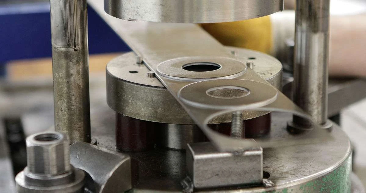
The press-and-sinter trade-off is between dedicated production tooling and the recurring advantage of making a suitable profile close to final shape. Geometry must permit filling, compaction and ejection; selected side features, threads or accurate faces may still need machining. Density gradients and fragile green handling also belong in the feasibility review.
For example, CSMFG's SS304L Holder / Halter has a reference price of RMB 4.40 above 10,000 pieces, based on the November 2026 part information. The stated requirements include 6.6 g/cm³ and 45 HRB. First compare the drawing and actual order pattern with the tool investment. Then include secondary features, inspection, yield and any finish in the complete accepted-part cost. A frequently revised prototype can favor another route, while a stable repeated profile may justify the die. The process comparison separates conventional compaction from MIM and explains why price comparisons must use matching component requirements.
How does the die affect design?

Powder must fill the cavity, compact to an adequate green density and be ejected without damage. A narrow, deep cavity or an abrupt step in height can create a difficult fill or a density gradient. Multi-level tooling can form some stepped parts, but each level adds a tooling and control consideration. Long thin walls and sharp transitions should be reviewed before ordering a die.
For a gear with a cross-drilled oil hole, compare a simple axial die with a secondary drilling operation against alternatives. The apparent extra operation may be less expensive and more reliable than unusually complex tooling. Include deburring and inspection of the finished hole in either quotation.
Which press-and-sinter problems should be checked upstream?
A low-density region, a tool-related mark or a contaminated powder blend can become a finished-part problem after sintering. Investigation areas include powder-batch variation, tool wear, compaction conditions and furnace atmosphere. A correction needs the actual material and tool evidence: increasing pressure or temperature indiscriminately can introduce another defect.
| Observation | Stage to investigate | Evidence to compare |
|---|---|---|
| Crack near a repeatable tool location | Powder filling, local density, tool cleanliness and ejection | Green samples, tool surfaces and sectioned parts |
| Dimensional drift | Tool wear, batch formulation and thermal processing | Dimensions by tool position, powder lot and furnace batch |
| Oxidation or property change | Atmosphere, thermal cycle and material chemistry | Furnace records and final chemistry or property tests |
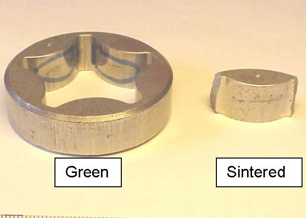
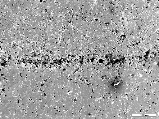
In the illustrated pressed-PM training example, a centerline crack was associated with a low-density, contaminated region. The investigation also identified insufficient local demagnetization of a core rod, which could retain iron-powder contamination.
That is a documented case mechanism to investigate when the pattern fits, not a universal explanation for every crack. Compare the green and sintered conditions and inspect the suspected tool location before changing a recipe.
How are parts checked?
A PM inspection plan is the set of checks that connects in-process control with the final component requirements. Green weight or dimensions may support process monitoring; final dimensions, density, hardness and relevant functional tests judge a different stage. The sampling and test condition should match the characteristic being accepted.
For example, the CSMFG SS304L Holder is specified at 6.6 g/cm³ and 45 HRB, and its drawing marks M6 in two positions. First identify whether the dimension or property applies after sintering, machining or a later finish. Then define the method, specimen or actual-part location, sample count and acceptance rule. CSMFG's November 2026 information supplies those Holder requirements, not a completed inspection dataset. A thread gauge, bulk-density method and local micrograph answer different questions. Keep the material lot and final operation associated with the recorded result so a dimensional pass is not mistakenly treated as proof of every material or functional requirement.
What does the Holder / Halter show about a complete PM route?
The CSMFG Holder / Halter is a practical press-and-sinter example with a specified SS304L substrate, 6.6 g/cm³ density and 45 HRB hardness. The supplied drawing marks M6 in two positions; the production photograph shows both sides of the repeated component geometry. According to CSMFG's November 2026 information, the reference unit price is RMB 4.40 for orders above 10,000 pieces.
The example connects powder selection to the finished drawing. First review whether the profile can be compacted and ejected; then identify which threads, surfaces or dimensions need later operations. CSMFG's documented post-sinter capabilities include sizing, coining, repressing, drilling, tapping, heat treatment and suitable finishing. The exact Holder operation sequence and price inclusions should be stated in the quote. A drawing callout and a product photograph do not replace an inspection record. See the illustrated cost example and secondary-operations guide.

How are raw-material changes and nonconforming powder controlled?
The factory's PM presentation describes incoming acceptance checks, periodic supplier evaluation and recorded disposition of nonconforming powder. Chemistry, particle-size distribution, apparent density and flowability are named checks. Dry storage and FIFO inventory control protect powder from moisture, contamination and accidental mixing before it reaches the press. Traceability should keep the relevant material identity available during defect investigation.
For example, the source Fe–Cu–C pinhole case changes copper powder from 100 to 200 mesh after microscopy identifies 100–150 µm cavities near copper-rich regions. A different crack case points to contamination retained at an inadequately demagnetized core rod. These findings explain why increasing press force alone is not a complete correction. According to the source cases, material distribution and tooling cleanliness must be examined with local density and the furnace route. The materials guide and sintering investigation keep those variables connected.
Powder metallurgy process questions
What are the main steps in press-and-sinter powder metallurgy?
Press-and-sinter is a conventional powder-metallurgy sequence of blending, die compaction, lubricant removal and sintering, followed by any required secondary work. First select and mix the metal powder, alloy additions and lubricant. Second compact the blend and eject a green component. The furnace route removes lubricant and develops particle bonds before final operations and inspection.
For example, the CSMFG Holder / Halter is a practical component context: SS304L, with 6.6 g/cm³ density and 45 HRB hardness specified in the November 2026 factory information. Its M6 thread callouts also show why the route may need operations beyond forming the profile. The MPIF conventional-process overview places compaction and controlled-atmosphere sintering at the center of the process. MIM belongs to the wider powder-metallurgy family but forms the initial shape by injecting powder–binder feedstock, so its molding and debinding stages should not be substituted for die pressing in a process description.
Can a powder metal part be machined or heat treated?
A sintered PM part is a candidate for selected machining and material-specific heat treatment when the final drawing requires them. Drilling or tapping can create a feature that is difficult to compact directly; sizing can calibrate a fit. The exact route depends on the alloy, porosity, geometry and required condition.
For example, the CSMFG Holder / Halter drawing includes two M6 thread callouts, while its specification names SS304L, 6.6 g/cm³ and 45 HRB. A different Cam Lever is specified in 17-4PH H900 and has an explicit drilled feature. According to the November 2026 factory information, these are different component routes, so the treatment for one should not be assigned to the other automatically. First identify what must change after sintering. Then plan machining, deburring, thermal processing and any finish with final inspection after the relevant operation. The secondary-operation guide explains the available choices and sequence effects.
Related reading: See MIM vs. conventional powder metallurgy, understand sintering and porosity, and review powder metallurgy materials.
For a manufacturability and sourcing discussion, visit CSMFG’s powder metallurgy services.
Continue with secondary operations after sintering and surface-treatment selection.